Spanning-Tree is a layer 2 loop detection mechanism for a switched network.
There are several spanning-tree standards
- 802.1D – STP
- 802.1W – RSTP
- 802.1S – MST
Cisco also has two proprietary types of spanning tree;
- PVST+ (Per-VLAN Spanning Tree)
- RPVST+ (Rapid Per-VLAN Spanning Tree)
One of the most important pieces of a spanning tree is electing a root switch. You can leave the election up to chance or “rig” the election how you want it and have the switch you want to be the root. The switches will hold an election to see who will be the root switch. Each switch will send out a BPDU (Bridge Protocol Data Unit) claiming to be the root. If a switch hears a superior hello with a lower BID (Bridge Identifier), the switch that hears the superior hello will stop claiming to be the root and pass the superior BPDU. Eventually, this will stop, and one switch will win the election.
The original 802.1D Bridge ID has two fields.
- A two-byte priority field is used if you want to “rig” the election.
- 6-byte MAC field, which is used as the tiebreaker, the lowest wins MAC wins
Original 802.1D Bridge ID

There was a format change to the BID to support PVST, MST, etc., to include the VLAN_ID in the election because, in PVST+, you can have a different STP instance per VLAN.

How is the root determined?
- The root creates and sends hello’s every 2 seconds.
- Each switch receives the hello and forwards the hello after updating the following;
- Cost
- Forwarding Switch BID
- Forwarding port priority
- Forwarding port number
- Nothing is forwarded out of ports in a BLK state
- Of all ports that receive hello’s, the port with the least calculated cost to the root is the RP
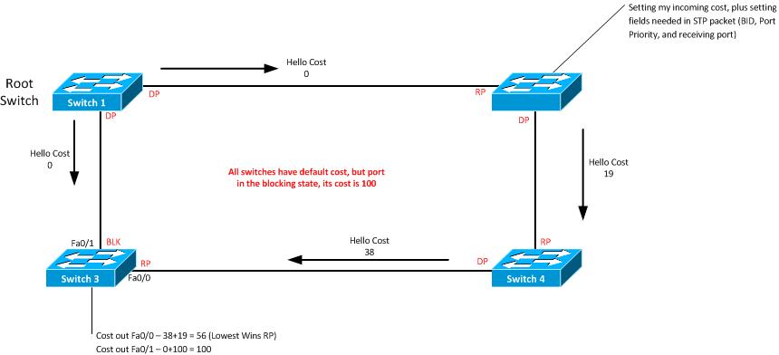
Looking at the above diagram, the root ports would be
- SW2, Fa0/0
- SW3 Fa0/0
- SW4 Fa0/0
802.1D Port Costs
| Speed | Original | New |
| 10mbps | 100 | 100 |
| 100mbps | 10 | 19 |
| 1000mbps (1gbps) | 1 | 2 |
| 10000mbps (10gbps) | 1 | 1 |
How to determine the Designated Port (DP)
Before determining what port is a DP, we need to know what a DP is. A Designated Port is the only port that forwards frames onto that LAN segment. T0 becomes a DP; a switch must send the hello with the lowest advertised cost. Usually, on the other end of the RP is a DP.
During all of this, what happens if there is a tie? The tiebreakers are;
- The lowest value of forwarding switch BID
- The lowest port priority of the neighboring switch
- The lowest interface of the neighboring switch
Converging a New Spanning Tree Topology
When STP has a stable topology, the following occurs
- The root switch generates a hello based on the hello interval
- Each non-root switch regularly (based on hello) receives a copy of the hello on the root port
- Each switch updates the BPDU and forwards it out to the designated port
- On each blocking port, the switch receives the BDPU from the designated port, but it will not forward it
When a link between SW1 (the root) and SW2 goes down
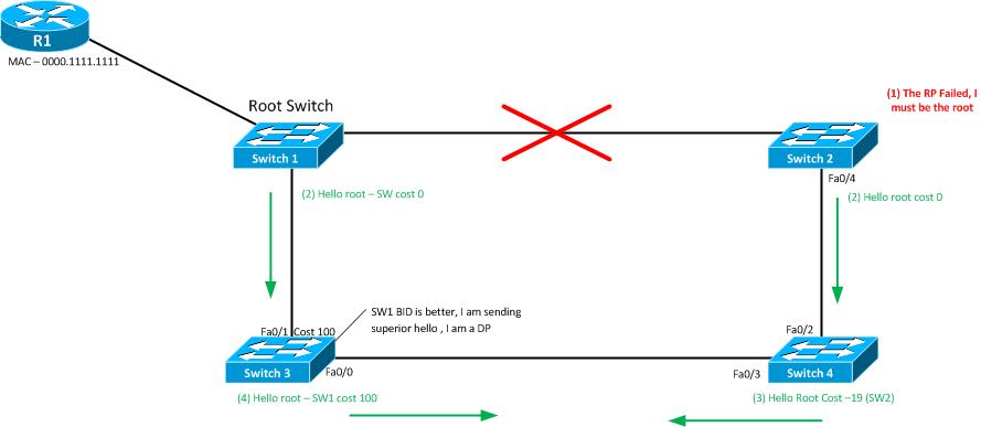
The key steps from the above diagram
- R2 stops receiving hello’s on RP.
- Because R2 is not reviving Hello’s, it begins a new election claiming to be the root.
- SW4 notices the latest hello implies there is a new switch trying to be the root; R4 ends up with the same RP (for now), updates the fields in the BDPU, and forwards the BPDU toward R3
- R3 receives the hello from SW4, but it is inferior to SW3 from SW1.
- SW1 is still the root bridge
The new port breakdown in this diagram is
- SW2 – Fa0/4: RP
- SW4 – Fa0/2:DP, Fa0/3:RP
- SW3 – Fa0/1: RP, Fa0/0: DP
Topology Changes
When an STP topology changes, other switches must know how to update their CAM tables. Two things need to happen for this to occur;
- All switches need to be notified to timeout their CAM entries
- Each switch uses a short-timer (forward-delay) to time out CAM entries
Any switch can send a TCN (Topology Change Notification) BPDU, which is sent toward the root switch. After the root receives it, the root switch will notify the rest of the switches using this process;
- A switch experiencing a port change sends a TCN BPDU out of its root port. This is repeated every hello interval until all devices acknowledge
- The next switch receiving that TCN BPDU sends back an acknowledgment via its next forwarded hello BPDU with its TCN bit set
- The DP on the segment from steps 1 and 2 repeats the first two steps, sending TCN BPDUs out of root ports and waiting for the acknowledgment from the DP on that segment.
A switch that receives a hello BPDU with the TCN bit set uses the forward-delay timer (15 seconds) to timeout entries in the CAM table.
Transitioning from Blocking to Learning
This is to prevent loops if they exist while the port is transitioning. The transition from listening to learning is 30 seconds (2x forward delay)
802.1D Spanning-Tree State Information
| State | Forwards Data Frames | Learns Source MAC of Received Frames | Transitionary or Stable |
| Blocking | No | No | Stable |
| Listening | No | No | Transitionary |
| Learning | No | Yes | Transitionary |
| Forwarding | Yes | Yes | Stable |
| Disabled | No | No | Stable |
New ports (RP/DP) must go from BLK –> Listening –> Learning–> Forwarding.
If you are going from Forwarding –> Blocking, that can happen right away
PVST
The per-VLAN Spanning-Tree creates a different STP instance for each VLAN configured on the switch. Traffic for each VLAN will be sent to the corresponding root so that VLAN1 traffic will go to SW1, and VLAN 2 traffic will go to SW.
Optimizing Spanning-Tree
Left to defaults if a root fails, STP 802.1D takes 50 seconds to reconverge (2o seconds max-age and 2x forward-delay for listening and learning stages). You can use portfast, backbonefast, and uplinkfast to optimize STP. These three optimization techniques are Cisco proprietary.
| Feature | Requirement for Use | How convergence is optimized |
| PortFast | Used on access ports not connected to up-links or other switches | Puts port in forwarding state once physically connected |
| UplinkFast | Use on access layer switches with multiple uplinks to core and distribution layer switches. | Immediately replaces lost RP with new RP. This is done with an alternate RP. |
| BackBoneFast | Used to detect indirect link failures, usually in the core | It avoids waiting for max-age to expire when its RP stops receiving hellos. This does so by querying the switch attached to the RP with an RLQ (Root Link Query) message where the missing hello should have arrived |
UplinkFast will set the following.
- Root Priority to 49,152
- Port Costs to 3,000
- Tracks alternate RP; these are ports on which root hellos are being received.
Rapid Spanning-Tree (RSTP)
Enhances the original 802.1D STP standard by improving convergence. The key components are;
- Only wait for three missed hellos (6 seconds) on RP before reacting.
- New process to allow transition: disabled –> bypass Listening –> Learning –> Forwarding
- Standard features include PortFast, BackBoneFast, and UplinkFast
RSTP Link Types
- Point-to-Point: connects a switch to another switch (full-duplex)
- Shared: connects a switch to a hub (half-duplex)
- Edge: end devices
Administrative State Differences between 802.1D and 802.1W
| State | 802.1D | 802.1W |
| Disabled | Disabled | Discarding |
| Enabled | Blocking | Discarding |
| Enabled | Listening | Discarding |
| Enabled | Learning | Learning |
| Enabled | Forwarding | Forwarding |
Multiple Spanning Tree (MST) 802.1S
Defines using multiple STP instances in a network that uses 802.1Q trunking. The benefits are;
- like PVST+, you can tune the parameters
- always uses 802.1W timers
- does not require an STP instance for each VLAN; a best practice design is one STP instance per redundant path
A group of MST switches is called an MST region. All switches in the same region should have the same configuration; if not, some anomalies can happen; for example, if you map VLAN 1-5 to MST instance 1 and VLAN 6-10 in MST instance 2, keep them in the same MST region. They have the same revision number and will be in different MST regions.
A benefit of MST is that if the MST region has hundreds of VLANs configured, it will only send one STP message for the whole MST region, whereas PVST+ will send hundreds of STP messages.
To prevent loops over CST (Common Spanning Tree) links connecting the MST region to the non-MST regions, MST participates in an STP instance with switches outside the MST region. This additional STP instance is called IST (Internal Spanning-Tree). MST regions look like a single switch outside the region
Protecting Spanning-Tree
- BPDUGuard: Configured per-interface – If a BPDU is received on the port, it puts the port in err-disable, requires admin intervention
- RootGuard: Configured per-interface – ignores any received superior BPDUs to prevent a switch connected to this port from becoming the root. If a superior BPDU is received on a port configured for RootGuard, it puts the port in a root-inconsistent state and stops forwarding and receiving frames until the superior BPDUs stop.
- UDLD: Uses layer 2 messages to decide when a switch can no longer receive frames from a neighbor. The side whose TX did not fail gets put in an err-disable state, which the admin can reset, or you can reset when traffic is flowing again.
- UDLD Aggressive: same as UDLD, but tries 8x to reconnect. If it fails, it puts both sides in an err-disable state, which the admin can reset, or you can reset it when traffic is flowing again.
- Loopguard: when normal BPDUs are no longer received, the port does not go through the normal STP convergence and is put in a loop-inconsistent state. Once normal BPDUs are received, they will transition back to normal operation.