IP forwarding is how packets go from one side of the network to the other. It is also known as IP routing.
So we can have a base understanding, let’s look at the diagram below. How does the R3 know how to forward the telnet packet to R1?
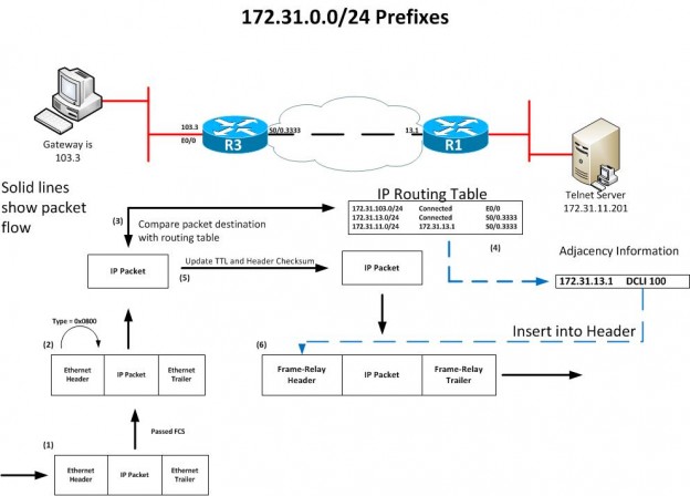
- R3 receives the frame and checks the Frame Check Sequence (FCS); if there are errors, the R3 will drop the packet without recovering it.
- If the FCS passes, the ethertype field is checked and extracts the IP packet, leaving the data-link header and trailer discarded.
- Assuming this is an IP packet, the router checks its routing table for the most specific match.
- The matched routing table entry includes an outgoing interface and the next-hop IP addresses. This information also points to the router adjacency information needed to build a new data link frame.
- Before the new frame creation, the router updates the IP header and decrements one from the TTL field, requiring a re-computation of the checksum.
- R3 encapsulates the packet in the new data-link header (this one being a Frame-Relay header and including the destination address) and a trailer (including a new FCS) to create the new frame and send it over the wire toward R1.
Fast Switching and Cisco Express Forwarding (CEF)
- Fast Switching: The first packet through the device will be process-switched, and all subsequent packets will be added to the fast-switching cache (AKA the route cache). A drawback of fast switching is the entries timeout quickly, per destination, not destination prefix.
- Cisco Express Forwarding (CEF): Overcomes the shortcomings of fast switching. Optimizes route lookup by constructing the Forwarding Information Base (FIB). The FIB is a copy of the IP routing table. When a packet arrives, CEF routers search the FIB when a match is found, that match points to the adjacency table (how and where a packet should be forwarded)
Matching Logic and Load balancing Options for each Switching Path
| Switching Path | Table Holding Forwarding Information | Load-Balancing Method |
| Process Switching | IP Routing Table | Per Packet |
| Fast Switching | Fast Switching Cache | Per destination IP |
| CEF | FIB and Adjacency table | Per hash of the source and destination IP or packet |
How is the adjacency table formed: with ARP or Inverse-ARP (InARP)
Frame-Relay Inverse ARP
Inverse-ARP (InARP) discovers the DLCI used to reach a particular adjacent IP address; this process differs from regular ARP on LANs that map IP addresses to MAC addresses. With InARP, routers already know the DLCI and need to learn the corresponding IP address.
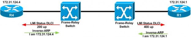
As you can see from above, the routers already know the DLCIs; once the router gets the LMI message for the DLCI, it will send an InARP out saying I am this IP address. This is in direct response to an LMI PVC up status message. If you disable LMI messages, InARP is also disabled because the router has no trigger to send the InARP message.
You can disable InARP; the commands are
To disable InARP altogether on an interface
R1(config)#interface serial0/0
R1(config-if)#no frame-relay inverse-arp
To disable InARP for a specific VC
R1(config)#interface serial0/0
R1(config-if)#no frame-relay inverse-arp ?
<16-1007> Set DLCI for inverse ARP
vc-bundle vc-bundle
Behaviors Related to Inverse ARP
| Behavior | Point-to-Point | Physical or Multipoint |
| Does InverseARP require LMI | Always | Always |
| Is InverseARP enabled by default | Yes | Yes |
| Can InverseARP be disabled | No | Yes |
| Ignores InverseARP messages | Yes | Only when Disabled |
Multilayer Switching
It uses layer 3 ports that consist of Routed (physical), Switched Virtual Interfaces (SVI), or layer 3 port channels. A routed port has the following characteristics;
- Not in any VLAN (including VLAN1)
- There is no layer 2 switching logic for that port.
- IP addresses are configured under the interface
- The adjacency table lists the outgoing physical interface or port-channel
Multilayer switching interfaces
| Interface | Forward to Adjacent Device | Create SVI, and layer 2 VLAN must exist |
| VLAN Interface | Layer 2 logic and layer 2 CAM table | Create SVI and layer 2 VLAN must exist |
| Routed Port (physical) | Forward out the physical interface | No Switchport |
| Layer 2 port-channel | N/A, just another layer 2 forwarding path | n/a |
| Layer 3 port-channel | Balances across links in the port-channel | No switchport and load balancing method |
Optimized Edge Routing (OER) and Performance Routing (PfR)
OER is the older way, and PfR is the newer way to extend the capabilities of routers to route traffic more optimally than routing protocols can. OER/PfR looks at;
- Packet Loss
- Response time
- Path Availability
- Traffic Load Distribution
OER uses a five-phase operational model;
- Profile: learn flows that have high latency and throughput
- Measure: collect traffic (passive or active), compute performance metrics
- Apply Policy: create low and high thresholds to define in-policy and out-of-policy (OOP) performance categories
- Control: influence traffic by manipulating routing or by using Policy-Based Routing (PBR)
- Verify: Verify OOP event performance and adjust to bring in-policy
PfR or PIRO (protocol-independent Route Optimization) has the following requirements and conditions.
- CEF must be enabled
- IGP/BGP must be functional
- Does not support MPLS, does not understand the MPLS header
- It uses the redistribution of static routes with a tag
PfR extends beyond OER because it can optimize traffic based on application. Attributes of PfR are;
- Optimizes traffic path based on application type, performance requirements, and network performance
- Controls outbound traffic using redistributed IGP routes
- controls inbound traffic in BGP by prepending AS through communities on select NLRI’s
- Logical link bundling
- Passive with Netflow
- Active with IP SLA
- Can operate in monitor mode only
- Can re-route traffic in 3 seconds
- Automatic path optimization
- Good Mode: alternate route when the defined threshold is reached
- Best Mode: always switches traffic to route with the best performance
Device roles in PfR
- Master Controller: (OER Master) the decision-maker in the cluster
- Border Router: (OER Border) slave to the MC, takes directions from the MC
In a small environment, your BR can be on an MC
Master Controller Availability and Failure Considerations
MC and BR keepalives are sent, and if the BR does not see MC keepalives, the BR will remove any added routes. For high availability, it is recommended to have more than one MC. PfR traffic classes can be;
- IP address
- DSCP value
- Port number
- Protocol type